- Wachter Space Blog about Security and Automated Methods/
- Posts/
- Software Engineering 2 Lecture Summary/
Software Engineering 2 Lecture Summary
Software Engineering 2 (SWT II) is the follow-up lecture to Software Engineering 1 and is held by Prof. Dr. Reussner. It focuses on software architecture, quality and development processes. The first part of this post is a lecture summary organized as self test questions for active recall. Below there are answers to the learning goals presented in the last lecture.
Design & Realization
Clean Coding
Lehman’s first law
A system that is used will be changed
Lehman’s second law
An evolving system increases its complexity unless work is done to reduce it
SOLID principles
Single Responsibility Principle
There should never be more than one reason for a class to change
Each responsibility deals with one core concern
Bad smells: Big class ⇒ Refactoring: Extract class
Open Closed Principle
Software entities should be open for extension, but closed for modification
Liskov Substitution Principle
Functions that use pointers or references to base classes should be able to use objects of derived classes without knowing it.
Interface Segregation Principle
Clients should not be forced to depend upon interfaces that they do not use
Dependency Inversion Principle
“A. High level modules should not depend upon low level modules. Both should depend upon abstractions. B. Abstractions should not depend upon details. Details should depend upon abstractions.” — R. Martin
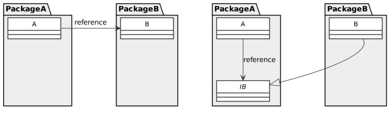
Why is it called dependency inversion?
An interface is used to invert the dependency between packages
Law of Demeter
“Don’t talk to strangers!”
A module should not know about the innards of the objects it manipulates.
Bad smell:
var value = getClassA().getClassB(). ... .getNeededValue();
Boy scout rule
Leave the code cleaner than you found it.
Clean-up at least one thing every time you make a modification
Principle of least surprise
Any function or class should implement the behaviours that another programmer could reasonably expect.
DRY principle
Don’t repeat yourself!
- Duplicated code fosters errors and inconsistencies
- Create methods to factor out\ common code
- Introduce parameters for specific behaviour
KISS principle
Keep it simple, stupid!
Make everything as simple as possible, but not simpler
YAGNI principle
“You ain’t gonna need it”
Only implement required features!
Single Level of Abstraction (SLA)
Statements within a function should be at the same abstraction level, if not, extract expressions/statements of higher detail into an own method.
Functions in a class: The abstraction level should decrease depth-first when reading from top to bottom.
Refactoring Definition
A disciplined technique for restructuring an existing body of code, altering its internal structure without changing its external behavior
The first rule in refactoring
Refactor with tests only!
When to refactor?
In general, when there are “bad smells” in the code.
- When you find yourself looking up details frequently
- What was the order of the method parameters again?
- Where was this method again and what does it do?
- When you feel the need to write a comment
- Try to refactor the code so that the comment becomes superfluous
- When you find yourself looking up details frequently
What is the relation of refactoring and performance
Refactoring may influence performance negatively however, Fowler recommends to do the refactoring first and the performance tuning on the cleaner code afterwards
Are there things that are difficult to refactor?
- Domain layer needs to be persisted
- Published interfaces
Order of implementation
Always move from the last coupled to the most coupled class
F.I.R.S.T. rules
The F.I.R.S.T rules of testing
- Fast: run them frequently
- Independent: Test cases should not influence each other
- Repeatable in any environment, so there is no excuse for failing tests
- Self-Validating: Tests either pass or fail automatically
- Timely: Tests are written right before production code
Software Architecture & Components
Software architecture definition
A software architecture is
- the result of a set of design decisions
- comprising the structure of the system
- with components and
- their relationships and
- their mapping to execution environments.
Relation of software architecture and software architecture documentation
This is the same. Software architecture is not the implicit structure of the system. Software architecture must always be explicitly thought of and documented.
Programming languages to document architectural decisions
Programming languages were never designed to document architectural decisions
Which three factors influence software architecture
- Organization
- Component reuses
- Requirements
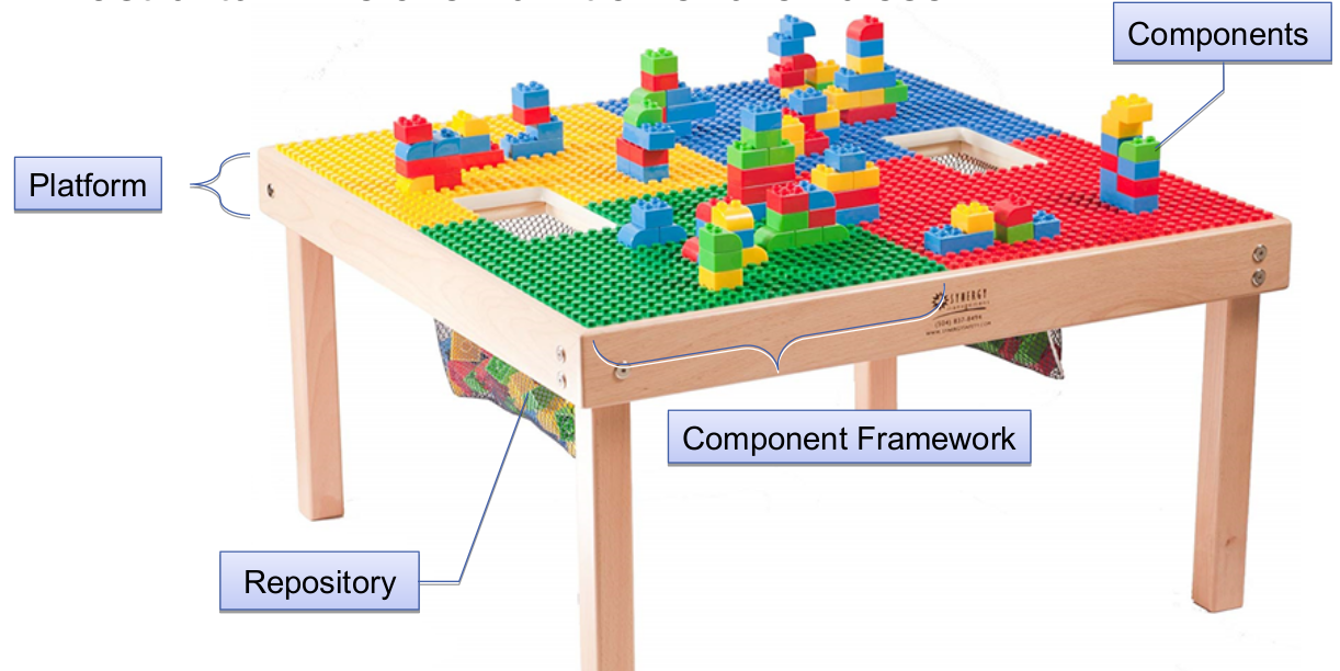
What elements form the component infrastructure
Relation of Views, View Types and View Points
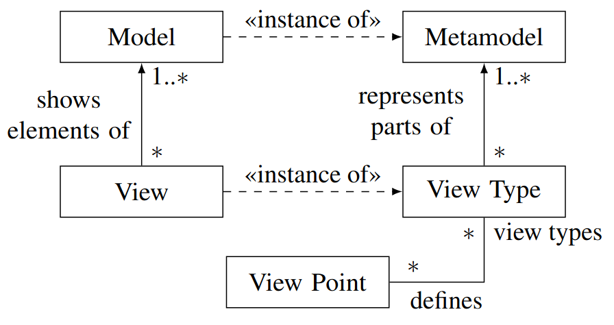
Examples of architectural views
4+1 views according to Kruchten, 1995:
- Logical view
- Functionality that the system provides to the end user
- Class diagram, communication diagram, sequence diagram
- Development view / implementation view
- Programmer's perspective on the software components
- Package diagram
- Physical view / deployment view
- System engineer's point of view
- Deployment diagram
- Scenarios / use case view
- sequences of interactions between objects, and between processes
- (Sequence diagram)
- Logical view
Advantages of an explicit architecture
- Stakeholder communication
- System analysis
- Large scale component reuse
- Project planning
What aspects of architecture decisions need to be recorded?
- Influential factors
- Decisions and why chosen
- Alternative solutions and why not chosen
Conway's Law
A system (usually) reflects the organizational structure that built it
Pattern definition
A proven solution for a recurring problem
Architectural pattern definition
Solution to a recurring problem where several forces have to be balanced at the architecture level
Architecture style definition
Solution principles (object-oriented style, modular style), independent of application, should be used throughout the architecture
Reference architecture definition
defines domain concepts, components and subsystems that can be used by concrete instances
Layered architecture
Advantages and disadvantages of layered architecture
- Advantages
- reduces accidental complexity
- improves modifiability
- clear separation of concerns
- independent exchangeability
- simplified testing
- Disadvantages
- usually increases the amount of classes
- Advantages
Reference architectures
- The architectural model of a system may conform to a generic reference architecture
- Reference models are derived from a study of the application domain
- It acts as a standard against which systems can be built and evaluated
- An awareness of these can simplify the problem of defining system architectures
- Example: OSI 7 Layer model
- The architectural model of a system may conform to a generic reference architecture
Clean Architecture
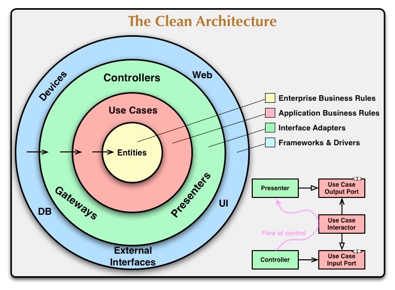
The “Clean Architecture” style
“The Dependency Rule”: Source code dependencies always point inwards
Claimed benefits of clean architecture
- Independence of Frameworks
- No dependencies on feature laden software
- Use advantages of frameworks with less of their disadvantages
- Testable systems
- Business rules testable without external elements (i.e. DB, UI)
- Independence of UI
- Change UI without changing rest of system
- Independence of Database
- Business rules are not bound to any DB vendor
- Independence of external agency
- Business rules do not know (and are independent of) the outside world
- Independence of Frameworks
Clean architecture entities
- Encapsulate business rules
- Object with methods
- Data structure set with functions
- Can be used as business object for applications
- Entity comparably stable against external changes
- Encapsulate business rules
Clean architecture application business rules
- Contains application-specific business rules
- Implements use cases of the system
- Defines data flow from and to entities
- Defines collaborations between multiple entities
- Changes of DB, UI or other externalities are not expected to affect UCs
- Layer is expected to be affected by changes to the operation of an application
- Use cases might change
- Therefore, code of the use case layer might change
Interface Adapters
Main concern: data exchange between layers
- Set of adapters
- Convert data
- From format most convenient for use cases and entities
- To format most convenient for externalities like DB and web
- Example: Contains MVC architecture of a GUI
- Contains views and controllers
- Models are often simple data structures passed from controllers to use cases and back to view
Examples of “Clean Architecture” Styles
- Hexagonal architecture
- Onion architecture
- Boundary/Control/Entity
How to refactor toward “Clean Architecture”
Dependency Inversion
Enterprise Application Architecture
Enterprise application (EA) definition
- Software application that supports businesses, in particular
- Support of business processes
- Process business transactions and data
- Mainly about display, manipulation, and storage of data
- Software application that supports businesses, in particular
Properties of enterprise applications
- Persistent data
- data lives longer than applications and hardware
- existing data needs to be integrated
- Large amount of data
- usually millions of records
- efficient access required
- Concurrent data access
- Can be hundreds of people at a time
- Concurrent access can cause errors (e.g. inconsistencies)
- Numerous different user interface screens
- both experienced and inexperienced users
- Interfaces to other systems
- integration with other enterprise applications
- different mechanisms: REST, SOAs, CORBA, batch files, ...
- Conceptual dissonance
- different people may understand the same term differently
- Complex business „illogic“
- business rules and processes are complex, but not necessarily logical
- often cannot be changed for development
- => consequence: Logic needs to change
- Persistent data
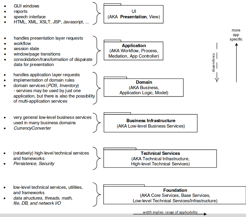
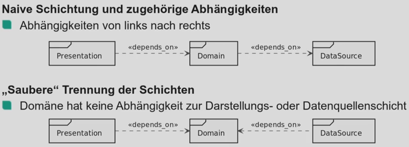
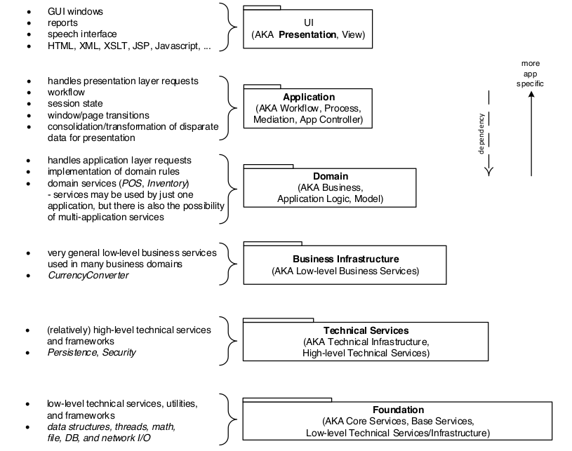
Layers of enterprise architecture
- Presentation (Front End)
- Handle interactions between user and software
- Display information
- Interpret commands
- Domain (Middle, Business)
- Work that application needs to do in the domain
- Calculations on data, what to load and store
- Data Source
- Communicating with other collaborating systems
- Example: Database
- Presentation (Front End)
EA pattern families covered
- Domain Logic
- How to represent the business rules?
- Data source architecture
- How to separate domain logic and data source?
- Object-relational structural patterns
- How to map objects to relational databases?
- Domain Logic
Transaction script
Domain logic EA pattern
Organizes business logic by procedures, where each procedure handles a single request from the presentation.
Advantages and disadvantages of transaction script
- Advantages
- Simple procedures that developers understand
- Easy to connect to simple data sources
- Transaction boundaries are easy to determine
- Disadvantages
- Does not scale well with complex logic
- Tends to have duplicate code
- Advantages
Domain model pattern
Domain logic EA pattern
An object model of the domain, that incorporates both behaviour and data
- Object-oriented thinking
- Identify concepts, and place logic with them
- Objects collaborate to do the transaction
Advantages and disadvantages of domain model
- Advantages
- Better organization of complex domain logic
- Disadvantages
- Steeper learning curve, if not familiar with OO
- Mapping to data sources more complex
- Advantages
Table module
Domain logic EA pattern
One instance to handle the business logic of all rows in a database table or database view
- Objects do not have identity
- Works with table-like data structure
Advantages and disadvantages of table module
- Advantages
- Straightforward mapping to data
- Separates logic for different concepts
- Useful if used technology supports it (COM, .NET)
- Problems
- No object instances: can be bad for complex logic
- Advantages
Record set
Data source EA pattern
- In-memory object that looks like the result of an SQL query, but
- can be easily generated
- and manipulated
- by all other parts of the system
- In-memory object that looks like the result of an SQL query, but
Table data gateway
Data source EA pattern
An object acts as a gateway to a database table. One instance handles all the rows in the table
- Simplest solution for DB access
- Aim: Separation of SQL statements
- Each methods maps the input parameters to an SQL statement and executes the SQL command
Gateway vs. Façade?
Façade
- Façade simplifies a more complex API
- Usually done by the writer of the service for general use
Gateway “An object that encapsulates access to an external system or resource”
- Idea similar to Façade
- But: Gateway is written by client for its particular use
Active record
Data source EA pattern
An object that wraps one row in a database table or view, encapsulates the database access, and adds domain logic on that data.
- OO approach: Bring data and functionality together provides an intuitive concept to represent data
- Each Active Record is responsible for saving and loading to the database
- Static finder methods wrap commonly used SQL queries and return Active Record objects
- Domain logic is in and acts on Active Records
Advantages and disadvantages of active record
- Good choice for very simple domain logic
- as it is easy to build and easy to understand then
- Database schema and Active Record need to be isomorphic
- i.e. there needs to be a 1:1 mapping
- Not to use with complex business logic
- with direct object relationships
- and inheritance
- … does not work well with Active Records
- as this would end up with very messy code
- use Data Mapper instead
- Good choice for very simple domain logic
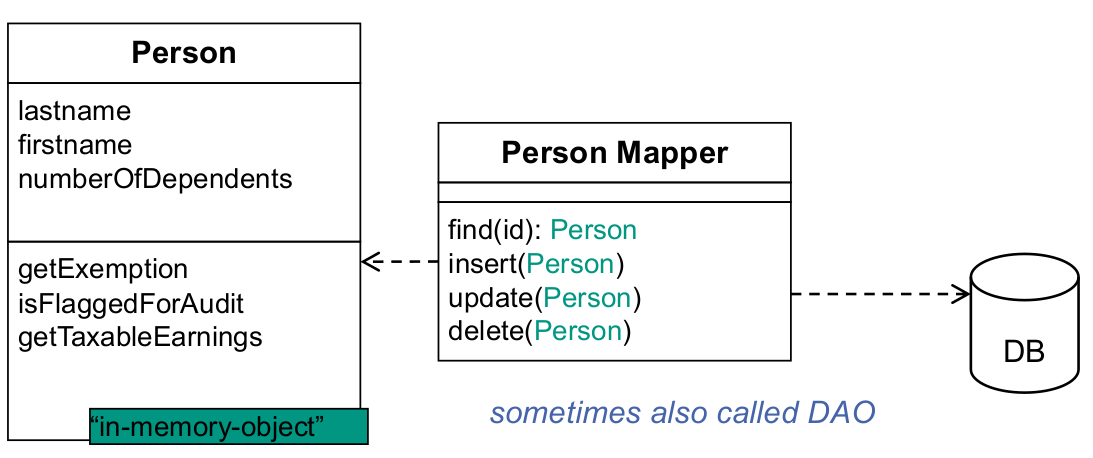
Row data gateway
Data source EA pattern
An object that acts as a gateway to a single record in a data source. There is one instance per row.
- Motivation
- putting database access code and in-memory-objects together (as in Active Record) increases complexity
- as it mixes database access and business logic
- Each DB table usually has one “finder” class
- each DB column becomes a field in gateway object
- each DB row gets one gateway object
- Person can even store its data there
- Motivation
Advantages and disadvantages of row data gateway
- Row Data Gateways are good candidates for code generation
- Database access code can be generated automatically
- Gateways shield domain layer from the database structure
- changing database structure becomes possible
- leads to (up to) three data representations: I. (business logic (domain model)) II. Row Data Gateway III. database
- Row Data Gateways are good candidates for code generation
Identity map
Data source EA pattern
Ensure that each object gets loaded only once by keeping every loaded object in a map. Look up objects using the map when referring to them.
Data Mapper
Data source EA pattern
A layer of Mappers that moves data between objects and database while keeping them independent of each other and the mapper itself.
Data Mappers should be generated with code generation
How to combine EA domain logic patterns and data source patterns
- Transaction Script
- Row Data Gateway: Explicit Interface, better to evolve
- Table Data Gateway: If Record Set framework
- Domain Model
- Simple: Active Record
- Complex mappings: Data Mapper
- Gateways couple model too tightly to DB schema
- Table Module (if Record Set framework)
- Table Data Gateway
- Transaction Script
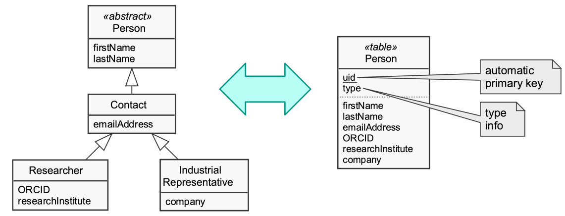
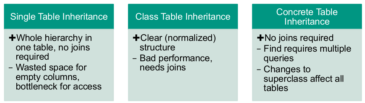
Single table inheritance
Object relational structural EA pattern
Represents an inheritance hierarchy of classes as a single table that has columns for all fields of the various classes.
Advantages and disadvantages of single table inheritance
- Advantages
- simple database schema: only one table
- no joins required
- refactoring that moves fields up or down do not require database changes
- Disadvantages
- direct use of tables confusing because of unused fields
- depends on actual data characteristics and database abilities to compress empty columns
- tables get very large
- many indexes & frequent locking → loss of performance
- solution: introduce additional index tables
- only one namespace for all fields exists
- for direct accesses, tables use naming conventions like “[Classname]_[Fieldname]”
- direct use of tables confusing because of unused fields
- Advantages
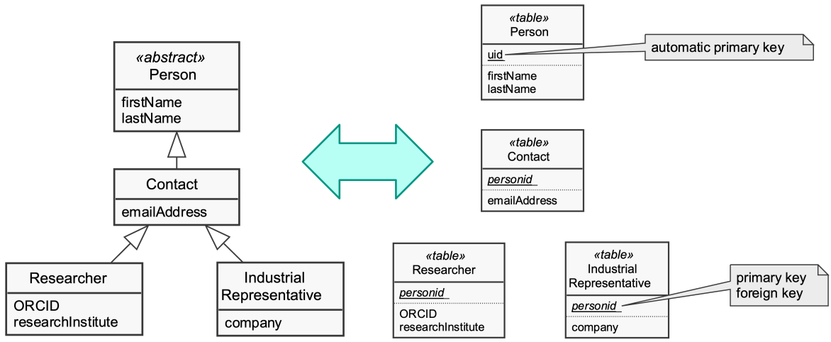
Class table inheritance
Object relational structural EA pattern
Represent an inheritance hierarchy of classes with one table for each class
Advantages and disadvantages of class table inheritance
- Advantages
- all columns relevant for every row
- tables are easier to understand
- tables do not waste space
- easier to map a legacy, pre-existing schema using this strategy
- straightforward relationship between domain model and database schema
- all columns relevant for every row
- Disadvantages
- loading an object in most cases means touching multiple tables
- Joining multiple tables, multiple queries -> Performance decreases
- refactoring: Moving fields up and down in the hierarchy implies changing the database schema
- supertypes can become bottlenecks
- has to be accessed frequently
- high normalisation makes schema harder to understand
- loading an object in most cases means touching multiple tables
- Advantages
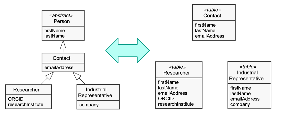
Concrete table inheritance
Object relational structural EA pattern
Represent an inheritance hierarchy of classes with one table per concrete class in the hierarchy
Advantages and disadvantages of concrete table inheritance
- Advantages
- each table is self-contained; no irrelevant fields
- useful, if applications directly access the database
- no joins required when reading from concrete mappers
- concrete subclasses
- only local access to tables can increase performance
- Each table is usually accessed by one domain object only
- each table is self-contained; no irrelevant fields
- Disadvantages
- refactoring: Pushing fields up / down requires database schema changes
- changes to field in supertypes influence all subtype tables
- query on superclass forces check on all subclasses (subtables) or complex join
- Advantages
Tradeoffs of object-relational structural EA patterns
Tradeoffs: Duplication of data vs. structure & speed
⇒ Mix patterns in a hierarchy depending on how usual access is
Compliance of enterprise architecture to clean architecture
Software Components
Software component definition
No universal definition, but generally something that can be composed.
Definition of the lecture: A component is a contractually specified building block for software which can be composed, deployed, and adapted without understanding its internals.
Why can a single object not be a component?
Inheritance is conflicting with the Black-Box-Principle of Components
Relation between components and layers
Components are feature-oriented, so they can span over multiple layers
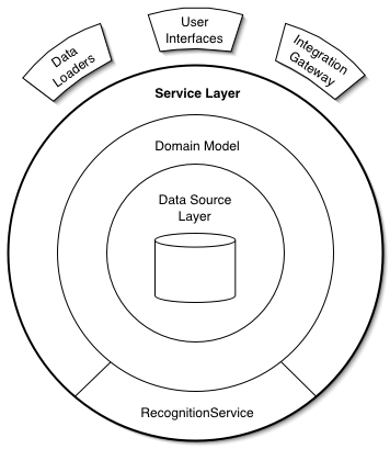
Service layer pattern
Defines an application's boundary with a layer of services that establishes a set of available operations and coordinates the application's response in each operation.
Component model idea
- Concrete realization of the principles of CBSE
- in practice, only components built for the same model can interoperate
- Defines –
- What a component is?
- How does a component offer services?
- How are components connected / composed?
- How do components communicate?
- Where can components be found?
- Often also providing an infrastructure for executing components
- sometimes denoted component framework
- Concrete realization of the principles of CBSE
OSGi
Open Service Gateway Initiative
- OO has driven modularisation to the extreme
- many fine-grained objects
- but no real module concept “above” packages
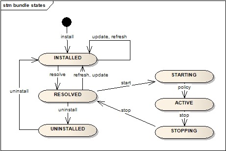
- OSGi offers bundles as a solution
- basically JAR files defining a public interface via a manifest
- provided services of bundles only usable when explicitly required in consumer bundle
- integrated into Eclipse
- OSGi provides a registry for services (bundles)
- only existing during runtime
- services can come and go
- OO has driven modularisation to the extreme
Web Services
Web services [...] are self-contained, self-describing, modular applications that can be published, located, and invoked across the Web. Web services perform functions, which can be anything from simple requests to complicated business processes.
(Web) services can be seen as deployed components
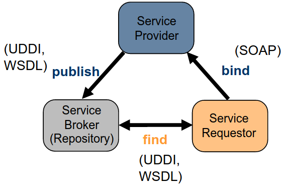
SOA
Service-Oriented Architecture
- service providers publish services by advertising service descriptions in service registry
- service requestors use find operation to retrieve service descriptions from service registry
- service requestors bind to service providers using binding information found in service descriptions to locate and invoke service
SEFF
Service effect specification
Description of the external visible actions of a component’s provided service Abstraction of internal behaviour Describes relationship between provided component side and required component side Can be parameterised by variables
Paladio contexts and roles
Mircoservices
Microservice definition
- Microservice is an architectural style.
- Microservice is an approach to develop a single application as a suite of small services
- Each application
- runs in its own process
- communicates with lightweight mechanisms (e.g., HTTP resource API, REST principles)
- Services
- are independently deployable
- are independently scalable
- can be written in different programming languages
- can be managed by different teams
Characteristics of a microservice architecture
- Note: Not all microservice architectures have all the characteristics!
- But, most microservice architectures exhibit most characteristics:
- Componentization via services
- Organized around business capabilities
- Products not projects
- Smart endpoints and dumb pipes
- Decentralized governance
- Decentralized data management
- Infrastructure automation
- Design for failure
- Evolutionary design
Tolerant reader
Ignore unknown elements and make minimum assumptions to increase robustness.
Principle for microservice design
Consumer-Driven Contracts
- Service implements union of all consumers needs the provider has to satisfy
- Call before actual service call specifies the actually needed service
- Contract: Data Schema, Service interfaces, Policies, ...
Principle for microservice design
Data management in the microservice architecture
- Microservices prefer letting each service manage its own database
- either different instances of the same database technology
- or entirely different database systems
- Yet, managing consistency becomes challenging
- Microservices prefer letting each service manage its own database
Design for failure
Microservice design pinciple
- Using services as components è applications need to be designed so that they can tolerate the failure of services
- Since services can fail at any time, it's important to be able to detect the failures quickly and, if possible, automatically restore service
- Microservice applications put a lot of emphasis on online monitoring of the application, checking both architectural elements (how many requests per second is the database getting) and business relevant metrics (such as how many orders per minute are received).
Advantages and disadvantages of microservices
- Advantages
- Strong Module Boundaries: Microservices reinforce modular structure, which is particularly important for larger teams.
- Independent Deployment: Simple services are easier to deploy, and since they are autonomous, are less likely to cause system failures when they go wrong.
- Technology Diversity: With microservices you can mix multiple languages, development frameworks and data-storage technologies.
- Disadvantages
- Distribution: Distributed systems harder to program, since remote calls are slow and are might always fail.
- Eventual Consistency: Maintaining strong consistency is extremely difficult for distributed system, which means everyone has to manage eventual consistency.
- Operational Complexity: You need a mature operations team to manage lots of services, which are being redeployed regularly.
- Advantages
Cloud Architecture
Cloud computing definition
Building on compute and storage virtualization, cloud computing provides scalable, network-centric, abstracted IT infrastructure, platforms, and applications as on-demand services that are billed by consumption.
Characteristics of cloud computing
- Elastic scalability
- On-demand self-service
- Ubiquitous network access
- Resource pooling
- Measured service
Scalability vs elasticity
Scalability is the ability of an application to counter high load through the utilization of more resources.
Elasticity is the ability of a resource management system to provide resources according to varying demand.
Multi-Tenancy and partitioning
Multi-Tenancy
- Isolation of workloads
- Separation of customers
- Customers gain administrative privileges
Partitioning of Resources
- Classical solution: Separation of servers => Physical Resource Sets (PRS)
- Cloud solution: Separation of services => Virtual Resource Sets (VRS)
Virtualization
Virtualization is the process of presenting computing resources in ways that users and applications can easily get value out of them, rather than presenting them in a way dictated by their implementation, geographic location, or physical packaging. In other words, it provides a logical rather than physical view of data, computing power, storage capacity, and other resources.
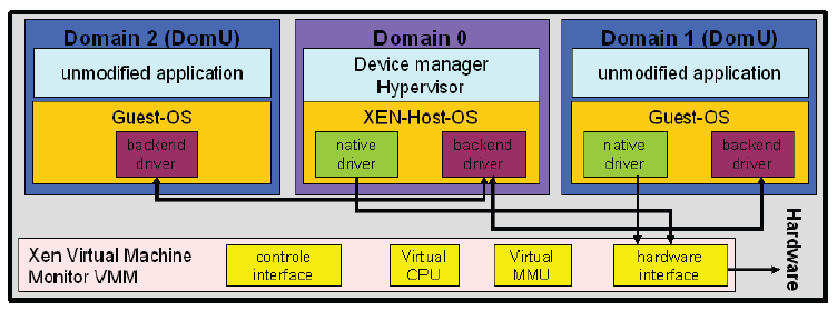
Paravirtualization
No emulated HW layer (like qemu), but guest OS use hyper calls (hypervisor interface calls)
Advantages of virtualization
- Consolidation: Improved energy efficiency
- Actual blade servers are able to host up to 100 VM images
- Availability
- Migration of VMs between blades on-line, without service interrupt
- Quality of Service (QoS)
- Service Level Agreements (SLA)
- Overbooking of resources (Thin provisioning)
- Decoupling of demand and resource provisioning
- De-duplication of storage: Store identical pages only once
- Logical view on resource pools improves management
- Capacity management rather than infrastructure management
- Automation of infrastructure operation and service delivery
- Almost no performance penalty with current technology
- Multicore
- Hardware virtualization (Intel VT-x (prev. Vanderpool), AMD-V)
- Consolidation: Improved energy efficiency
Cloud computing delivery models
- Software as a Service (SaaS)
- Web Applications like Google Apps, Salesforce etc.
- Platform as a Service
- Development or execution environments like e.g. Google App Engine, Windows Azure
- Infrastructure as a Service
- Offerings like Google Storage, Amazon Web Services etc
- Software as a Service (SaaS)
Total Cost of Ownership (TCO) of License-based Software Delivery
- Software licenses
- Hardware costs
- Software updates, update contracts
- Patches and fixes
- Backups
- Incident & Change Management
- Systems monitoring and management
- Ensuring availability, reliability, etc
- Human resources
- Energy costs
- etc.

Software License-based Delivery vs. SaaS
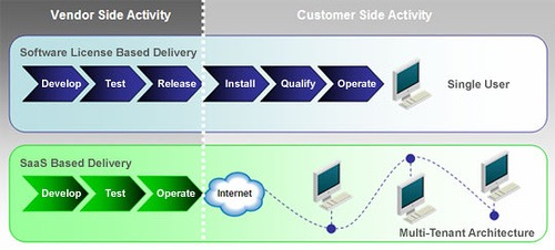
Key characteristics of SaaS
- Network-based access to, and management of, commercially available software
- Activities that are managed from central locations rather than at each customer's site, enabling customers to access applications remotely via the Web
- Application delivery that typically is closer to a one-to-many model (single instance, multi-tenant architecture) than to a one-to-one model, including architecture, pricing, partnering, and management characteristics
- Centralized feature updating, which obviates the need for downloadable patches and upgrades
Service Deployment Models
- Private cloud: Customer and provider belong to the same organization
- Public cloud: Customer and provider belong to different organizations
- Hybrid cloud: Combination of private and public cloud
- Community cloud: Stakeholders share resources to achieve common goal
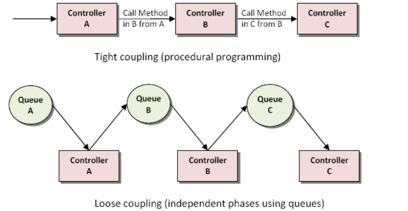
Using Queues for Loose coupling
- Principle: For better manageability and high-availability, make sure that your components are loosely coupled
- Components can fail independently, queues buffer until back up
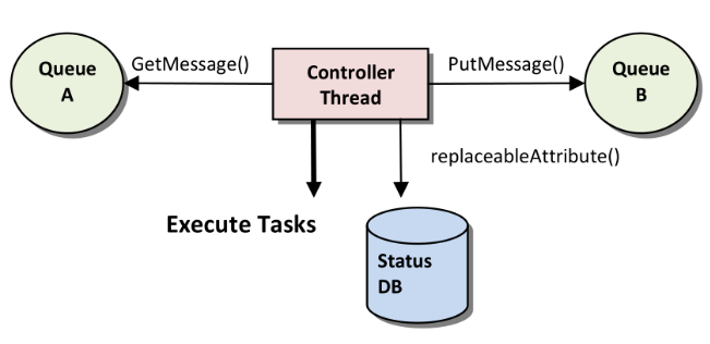
Simple Controller Architecture for Resilience
- After designing the basic functionality, ask “What if this fails?” for resilience
- Controllers externalize their state and thus can be resumed after failure
- Visibility timeout in message queues: Messages become visible for other consumers if original consumer fails
Guidelines for Cloud Applications
- Ensure that your application is scalable by designing each component to be scalable on its own.
- For better manageability and high-availability, make sure that your components are loosely coupled
- Implement parallelization for better use of the infrastructure and for performance
- After designing the basic functionality, ask the question "What if this fails?” for resilience
- Don't forget the cost factor. The key to building a cost-effective application is using on-demand resources in your design.
Software Container
Container definition
- Container are portable file systems containing:
- Application code
- Runtime environment
- System tools
- System libraries
- can be directly run on one host
- provide features via system services
- Container are portable file systems containing:
OCI Container Runtime Specification
- Standardization of
- Container configuration, execution environment,
- Container life cycle, and
- Container image
- Reference implementation within
runc
- Standardization of
File System Layers
- Simply zipping runtime and system libraries of a container creates large binaries
- Different containers share most system libraries and only differ in runtime libraries and application binaries
Solution:
- Create archive for system libraries and track file system changes in separately applicable archives
- employ an unioned File System
- composed of layers of archives
What do standardized container images contain?
- Image Manifest
- File system layers
- Image Index
- Container Configuration
Domain Driven Design
DDD steps
- Identify bounded context of application domains
- For each application domain
- Extract the application domain‘s ubiquitous language
- Distill domain model from that language
- Reflect this model in working software using building blocks
- Employ layered architecture to develop domain application
- Deploy and Link domain application as indicated by context map
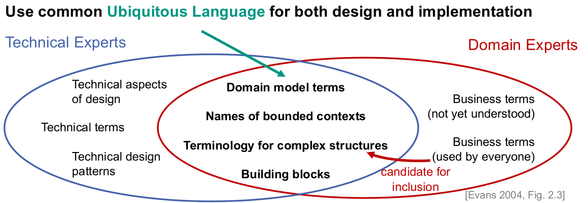
Ubiquitous Language
Bounded Context
- Declares definitional boundary for ubiquitous language
- Depends on
- Application domain (e.g., actors supported by application)
- Team organization (e.g., number of teams working on project)
- Physical manifestation (e.g., code base and database schemas)
- Strictly enforce consistency of ubiquitous language and domain model within bounds
- Focus on issues inside your boundary
- “don’t be distracted or confused by issues outside.” [Evans 2004, p.336]
- Define relations between bounded context in context map
- Which entities are shared?
- Which domain events are send between them?
DDD building blocks
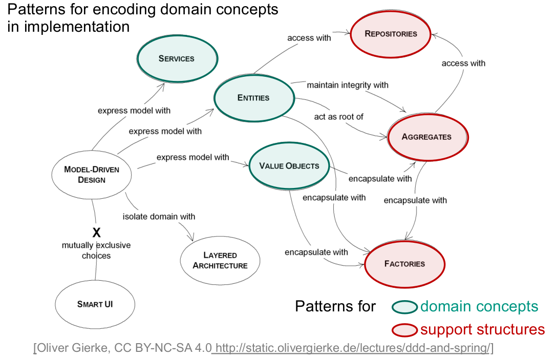
Entity
“Many objects are not fundamentally defined by their attributes, but rather by a thread of continuity and identity.” – [Evans 2004, pp. 89]
Entity denotes domain concepts
- with a unique identity
- established upon its creation; preserved during store, load, and transmission
- (usually) not defined by its attributes
- with continuity throughout its life cycle
- traceable / accountable throughout application
- distinction relevant for domain users
- with a unique identity
Value Object
“Many objects have no conceptual identity. These objects describe some characteristic of a thing.“ – [Evans 2004, pp. 97]
Value Object denotes domain concept
- “that describe other things”
- without identity
- identity derived from attributes
- distinguishable only by attributes
- that are immutable
- permits safe sharing, duplication, and distribution
- changeably by full replacement
DDD Service
“Sometimes, it just isn't a thing. Some concepts from the domain aren't natural to model as objects.” – [Evans 2004, pp. 104]
Service denotes domain concept
- that encode functionality
- not uniquely assignable to entity of value object
- carries meaning in domain model
- Interface defined in terms of entities and value objects
- that is stateless
- regardless of complexity of operation / transformation
- permits easy access and distribution
- that encode functionality
DDD Aggregate
“Aggregates mark off the scope within which invariants have to be maintained at every stage of the life cycle.” – [Evans 2004, pp. 135]
Aggregate clusters related entities and value objects
- defines boundaries around specific root entities
- root entity serves as Façade to access enclosed elements
- identity of aggregate derived from root entity
- removal of root removes complete aggregate
- ensures invariants and concurrent access
- prohibit references to elements other than its root
- changes to aggregate only through root ensuring invariants
- constructed as a whole satisfying invariants
- locking strategy decided for whole aggregate
- defines boundaries around specific root entities
DDD Factory
“When creation of an object, or an entire aggregates, becomes complicated or reveals too much of the internal structure, factories provide encapsulation.” – [Evans 2004, pp. 136]
Factory provides means to create domain concept
- that hides complexity of object construction
- creation of aggregates / related objects in atomic operation
- ensures that products’ invariant holds
- that separates construction concern
- extracted into separate domain concept
- only factory depends on aggregate’s internal elements
- that hides complexity of object construction
DDD Repository
“[…] we must have a starting point for a traversal to an Entity or Value in the middle of its life cycle.” – [Evans 2004, pp. 147]
- Repository permits finding domain concept
- simulate collection of entities or aggregates
- allows for accessing all, subsets or individual items
- provides implementation for complex queries
- usually backed by persistence mechanism
- database permits efficient querying
- handles reconstitution of entities and aggregates
- exposes simple method to store entities/aggregates, if any
DDD Modules
“The Modules in the domain layer should emerge as a meaningful part of the model, telling the story of the domain on a larger scale.“ – [Evans 2004, pp. 109]
Modules divides concepts in a domain model
- low coupling to other modules
- limit concepts to those required for understanding
- Separate concepts independent of model
- high cohesion within them
- combine closely related/dependent concepts
- contain cohesive set of concepts
- denotes a high-level domain concept
- low coupling to other modules
Types of DDD domains
- Core Domain [Evans 2004, pp. 400]
- crucial aspect of domain model to solve domain-related problem
- all other domains support core domain
- Shared Kernel [Evans 2004, pp. 354]
- domain concepts shared between different domains
- maintained and evolved by multiple teams
- requires effort for coordination and integration
- Supporting Domain
- encompasses concepts extracted from core domain
- domain concepts playing a support role for core domain
- Generic Subdomain [Evans 2004, pp. 406]
- encapsulates most generic concepts not belonging to core domain
- could be outsourced or replaced with off-the-shelf components
- Core Domain [Evans 2004, pp. 400]
Interactions between DDD domains

Model driven development
Abstract syntax
The abstract syntax of a metamodel describes the constructs of which models consist, as well as their properties and relations between them. This description is independent of the concrete depiction of these constructs, properties, and relations.
The modelling is done via metaclasses that define these concepts. It however does not show a concrete model or a concrete UML diagram type.
Concrete syntax
The concrete syntax describes the depiction of constructs, properties, and relations that are specified in the abstract syntax. For the abstract syntax of a metamodel, at least one concrete syntax must be specified, and arbitrarily many can be specified.
Examples for concrete constructs are sequence diagram, textual description, class diagram, …
Processes and Requirements
Brooks law
Adding more people to a late project makes it later
Boehm’s First Law
Error are more frequent during requirements and design
Parnas Law
Only what is hidden can be changed without risk
Reviews
Review definition
Reviews are meetings where a software artefact is examined to improve its quality, especially correctness (i.e. to remove errors)
Effectiveness and adoption of reviews
- Rigorous inspections can remove up to 60 – 90 % of errors before testing is started
- However, almost no one does them
Dangers of reviews
- Testing is omitted
- Authors are frustrated or even feel violated ⇒ ofuscated code
- Authors tend to get sloppy ⇒ “Errors will be found during review anyway.” (Like with testing, it is not true cleanroom software-engineering is successful)
Benefits of well done reviews
- Quality, correctness
- Reviews are a verification technique!
- Improved understanding on project
- Knowledge is shared in a better way
- Less dependency on availability of one person
- Teaching of style and experience to novices
- Better readability
- Less tricky code
- Better documentation / comments
- Quality, correctness
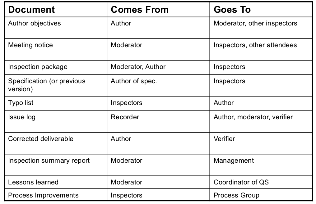
Phases of a Review
- Planning
- Overview
- Preparation
- Meeting
- Rework
- Follow-Up
- Causal Analysis
Roles and process of a review
Development processes
Problems of the “code and fix” approach
- badly structured code
- non-systematic improvements
- no real team work, as tasks can not be planned
- => Guru needed, no scalability of project size, dependability on one person
- missing design and documentation
- complications in maintenance
What are typical advantages of processes?
- lower project risks
- higher product quality
- better maintainability
Software process model
- Software process model is an abstract representation of a software development process
- I.e. it recommends guidelines for –
- which activities should be carried out
- how and in what order are they carried out
- i.e. defines phases and milestones
- who has to carry out what
- i.e. determines roles and responsibilities
- which products should be built until when
- i.e. denotes artefacts, documents, and other work results
- and sometimes even state which techniques and tools should be used
- which activities should be carried out
Waterfall Model
Life cycle model
- Planning
- Definition
- Design
- Implementation
- Testing
- Usage and maintenance
Problems of the waterfall model
- Users requirements often change
- Changes invalidate plan, design, and/or implementation
- Waterfall lacks feedback cycles for replanning, redesign, …
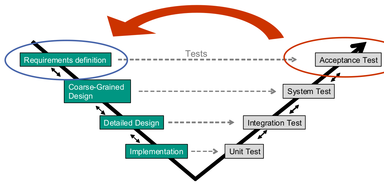
V-Model
- A model to show different software artefacts and their relation
- Not a (good) process model
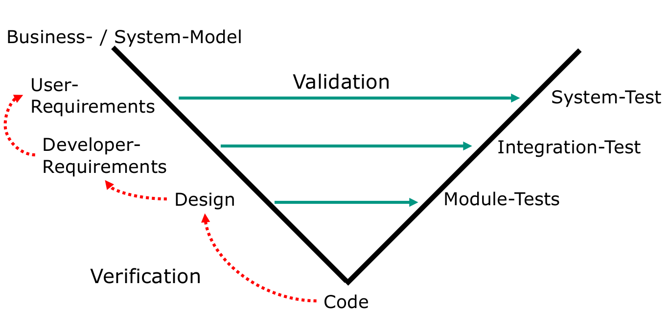
Validation and verification
- Validation: case based check on expected behaviour.
- Verification: check whether refinement relation holds between two documents:
- Requirements specification and code
- Requirements specification and architecture / design
- Architecture / design and code
UP overview
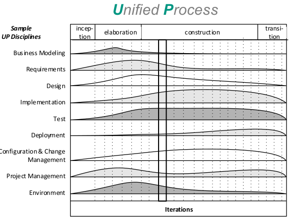
- The UP defines –
- 4 abstract phases
- to be concluded with a milestone
- not equivalent to waterfall phases!!!
- 9 disciplines
- 6 engineering + 3 supporting
- here we find our “mini waterfalls”
- 4 abstract phases
- The UP defines –
Goals of UP
Unified process is supposed to be –
- iterative und incremental
- risk-driven
- client-driven
- architecture-centric
UP Phases
Inception (Anfangsphase)
- “Envision the project scope, vision, and business case” [Larman]
- Explore the following kind of questions:
- „What is the vision and business case for this project?
- Feasible?
- Build and/or buy?
- Rough unreliable cost range: is it $10K – 100K or in the millions?
- Should we proceed or stop?” [Larman] Elaboration (Ausarbeitungsphase)
- “is the initial series of iterations during which, on a normal project,
- the core, risky software architecture is programmed and tested
- the majority of requirements are discovered and stabilized
- the major risks are mitigated or retired” [Larman]
- “Build the core architecture, resolve the high risk elements, define most requirements, and estimate the overall schedule and resources” [Larman] Construction (Konstruktionsphase)
- “Iterative implementation of the remaining lower risk and easier elements, and preparation for deployment” [Larman]
- Transition (Übergabephase)
- “beta tests, deployment” [Larman]
UP Disciplines
- Business Modelling
- “to understand and communicate the structure and the dynamics of the organization in which a system is to be deployed” [Larman]
- Mainly domain concepts and business processes
- Requirements
- Requirements engineering activities: Elicitation, analysis, documentation, validation, management
- Possible artefacts: Use-Case models, other requirements, glossary, vision statement, business rules
- Design
- Plan how to realize system in software, object-oriented analysis
- Model software classes as opposed to real world concepts
- Main artefacts: Software classes, behaviour models, architecture
- Implementation, Test, Deployment
- Configuration & Change Management, Project Management, Environment
But: no strict rules what to do!
- Business Modelling
RUP
Rational Unified Process
- The RUP is a specific implementation of the UP
- provides a disciplined approach for assigning tasks and responsibilities within an organization to develop specific products
- roles -> who?
- defines a set of skills and responsibilities
- activities/tasks -> how?
- describes work packages that need to be carried out by a role to achieve a result (i.e. a product)
- are implemented in disciplines (a.k.a. workflows) in each iteration
- artifacts/work products -> what?
- results of a task, e.g. models and documents
- roles -> who?
- provides a disciplined approach for assigning tasks and responsibilities within an organization to develop specific products
- The RUP is a specific implementation of the UP
RUP best practices
- Develop software iteratively
- Manage requirements
- Use component-based architectures
- Model software visually
- Verify software quality
- Control changes to software
Advantages and problems of processes
- Good:
- Phases help to structure project
- Divide and conqer of big task into smaller steps
- Roles support specialisation, help to define focus and responsibilities
- Good to have an overview on usually important activities / tasks.
- Problematic:
- If planning and realisation are strictly separated, it assumes a stable world. This assumption is most often wrong.
- Roles can lower productivity, as not every role is equally needed at any time.
- There is „optimum“ in the relation between (long term) costs and process complexity (including creating non code artifacts)
- Good:
Agile development
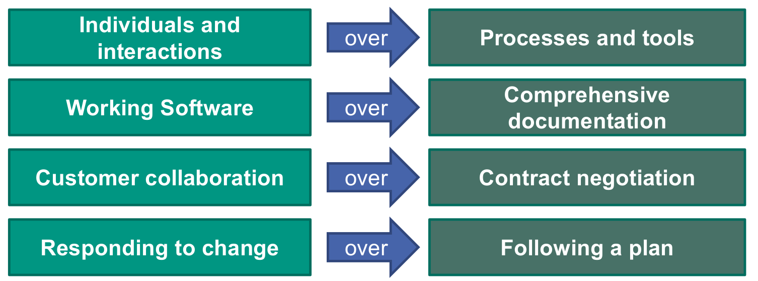
Values in the agile manifesto
XP values
- Communication
- Simplicity
- Feedback
- Courage
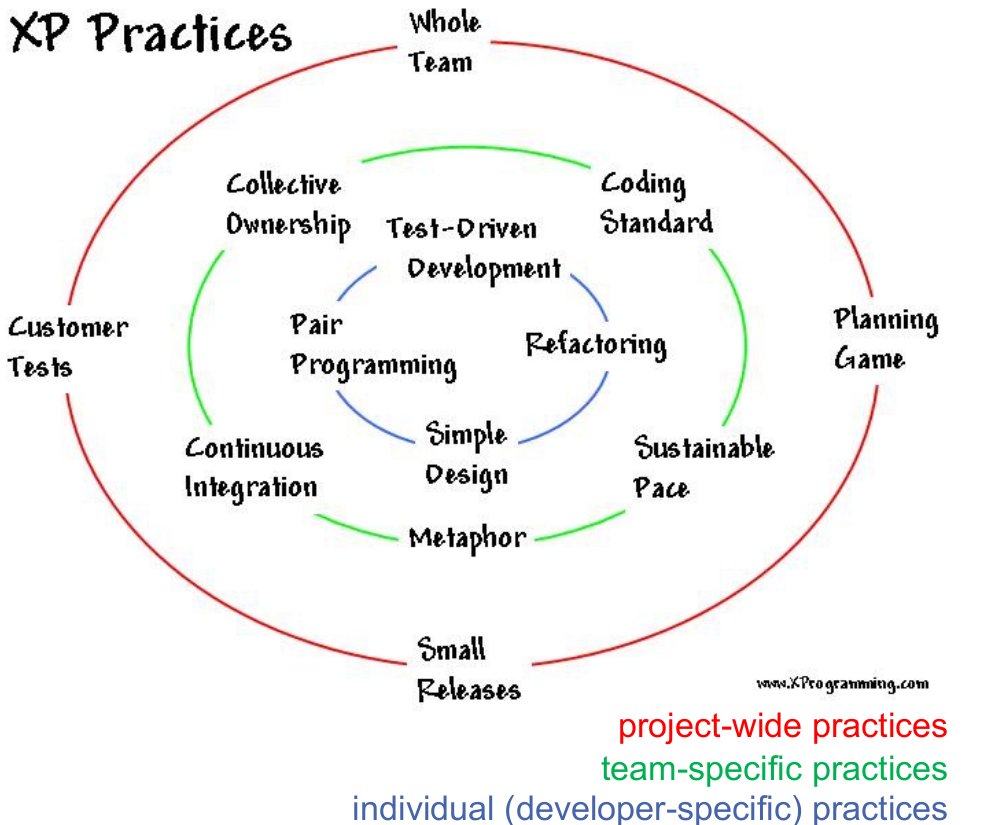
XP practices
Scrum meetings
- Sprint Planning
- is used to develop a detailed plan for the iteration
- Sprint Review
- demonstrate potentially shippable code, developed during the sprint
- Daily Scrum
- share information (through 3 questions!)
- discover dependencies
- adjust the work plan
- address individual needs and identified problems
- Sprint Retrospective
- assesses the work in sprint, identifies good and bad practices
- Sprint Planning
Scrum roles
- Product Owner
- responsible for the system
- decides which system increments make up a release
- Team (member)
- develops the software
- decides how many requirements can be implemented in a sprint
- Scrum Master
- supports in applying Scrum correctly
- assists in the continuous improvement of productivity
- Product Owner
Product backlog
A high-level collection of all features, etc. prioritized by business value
- contains all known requirements and work results, which have to be implemented in order to achieve the project goal
- these Product Backlog Items are usually expressed as user stories
- no activities (activities belong to the Sprint Backlog)
- annotated with story points for expressing the expected effort of an item
Sprint backlog
The Sprint backlog contains all requirements (user stories) the team has committed to deal with in the sprint planning meeting
- Taken from the product backlog
- decomposed into developer tasks
- To do, in progress, finished updates
- potentially newly arising tasks are estimated and added to the sprint (or even the product) backlog
- it is not allowed to add new requirements (user stories) in the middle of a sprint to the sprint backlog
- Only add activities as long as 85% of the net capacity of the team is not reached
Scrum project planning
- Scrum does not utilize a release or project plan in the traditional sense
- experience tells us that it is unrealistic to plan for all contingencies
- months or even years in advance
- however, estimates of cost and duration of the project are necessary
- experience tells us that it is unrealistic to plan for all contingencies
- Scrum thus applies planning on 3 levels –
- release planning which is a coarse forecast based on
- the product backlog
- the team's development velocity
- sprint planning
- planning of a workday
- release planning which is a coarse forecast based on
- Scrum does not utilize a release or project plan in the traditional sense
How to do Scrum for a large project
- observe Brook’s Law
- adding new people reduces the velocity in the first place
- start small and grow organically
- one team with talented people acquires the project’s foundation in a few sprints
- this team is split at the end of a sprint and new people are added
- prefer to add one team at a time (every 2-3 sprints)
- a more rapid growth is probably feasible, but is riskier as well
- minimize dependencies between teams
- feature over component teams
- try to have Area Product Owners
- meet for a daily Scrum of Scrums
- which is a daily scrum with representatives from each team
- observe Brook’s Law
How to do Scrum in a distributed project
- A project is considered being distributed as soon as team members work at different locations
- and cannot attend one common Daily Scrum easily
- Some important hints for these projects are –
- there is nothing like personal communication
- can’t you avoid the distribution?
- never separate the Scrum Master and the team
- try to have a product owner with the team as well
- distribute teams stepwise (analogous to the growth in large projects)
- have a core team that works together for a few sprints
- its members become the nuclei for two distributed teams
- exchange delegates between the teams from time to time
- in order to facilitate collaboration
- and allow the people to get acquainted personally
- there is nothing like personal communication
- A project is considered being distributed as soon as team members work at different locations
Advantages and disadvantages of agile methods
- Good:
- Agile projects do not assume a stable world.
- Fast feedback on customer satisfaction and product quality essential
- Disciplined Process (certainly not ad hoc!)
- Shifts responsibility to each team member.
- Problematic:
- Unclear how to include architectural design in agile projects.
- Unclear how to scale to larger projects, unclear how to do planned reuse.
- “Keep the architecture flexible” is not the complete answer, as some design
- decisions are by nature hard to revert.
- Shifts responsibility to each team member (not everyone wants to live with this pressure)
- Some dogmatism: relevance of scientific empirical evidence sometimes neglected: e.g., pair programming helps to improve quality early. However, they are less cost-effective than reviews (which help likewise in quality).
- Agile methods are a good manufacturing approach. But can we become an engineering discipline?
- Good:
Requirements engineering
Basic criterion for good requirement definitions
It should be possible to deduce good acceptance tests from the requirements definition
Facets of concern-based classification
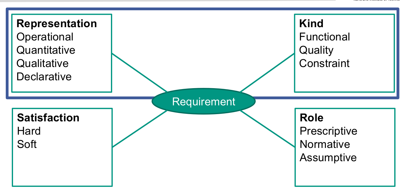
- Kind: based on concern
- Representation: How is it written down?
- Satisfaction: When is it fulfilled?
- Role: describes system-to-be (prescriptive), environment (normative), or actor (assumptive)
Concern-based classification: Kind of requirement
- A concern is a matter of interest in a system.
- A concern is a functional or behavioural concern if its matter of interest is primarily the expected behaviour of a system or system component in terms of its reaction to given input stimuli and the functions and data required for processing the stimuli and producing the reaction.
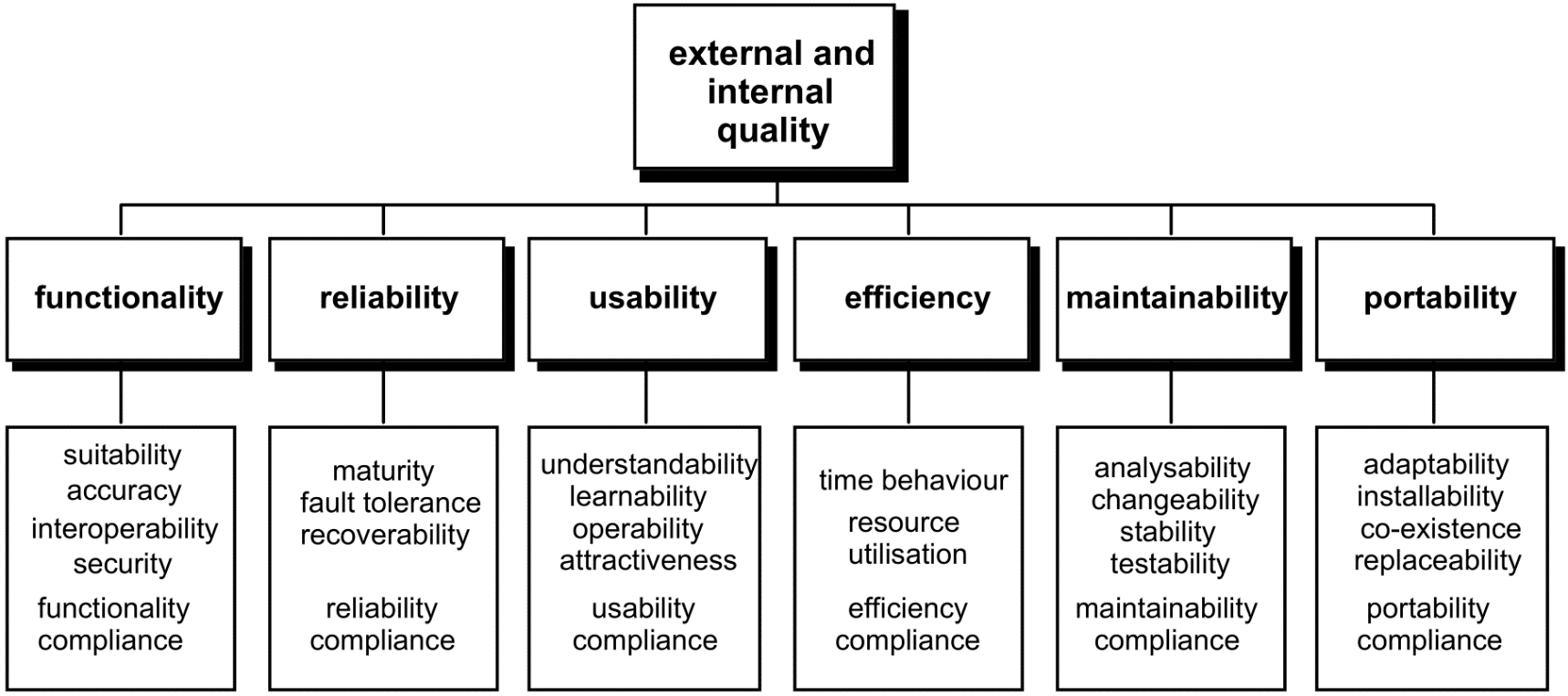
- A concern is a quality (non-functional) concern if its matter of interest is a quality of the kind enumerated in ISO/IEC 9126 [or in another quality model].
- Performance
- Reliability
- Usability
- Security
- Availability
- Portability
- Maintainability
- Constraint: constrains the solution space beyond what is necessary for meeting the given functional and quality requirements.
- Physical
- Legal
- Cultural
- Environmental
- Design and implementation
- Interface
Concern-based classification: Requirements representation
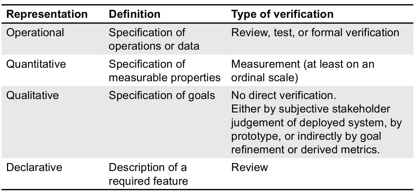
Advantages of concern-based classification
- Better understanding, less unnecessary discussions
- Appropriate validation techniques according to representation
- The view, that a single requirement can be represented differently, fits to the view on architecture to provide means to realise quality requirements.
- What are just specific operational representations (to be changed) and what are qualitative / quantitative goals as agreed with other stakeholders
Properties of good software requirements
- Adequate
- describes what the user wants or needs
- Complete
- nothing is missing
- Consistent
- no contradictions
- Understandable
- for developers and stakeholders
- Unambiguous
- no wrong interpretation
- Verifiable
- Suitable for the risk
- Detail and comprehensiveness based on how likely and how severe to get them wrong
- Adequate
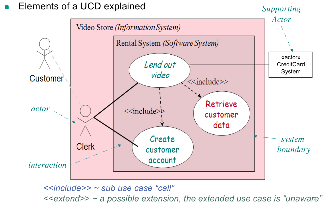
Use cases
Use case definition
- In general, use cases are a notation to textually capture an interaction of (typically) two parties
- in our context a use case typically captures a story of how a system is used by a user
- can also be another computer system
- use cases therefore focus on operational requirements (often functional)
- In the context of software development, the term usually denotes a "black-box user goal use case"
Optimal granularity of use cases
Use cases should be elementary business processes (EBPs)
A common mistake is defining many use cases at too low a level ⇒ Make them sub use cases of an EBP
EBP definition
Elementary Business Process
In business process engineering an EBP is defined as –
- a task
- performed by one person
- in one place at one time,
- in response to a business event,
- which adds measurable business value
- and leaves data in a consistent state
Heuristics for valuable use cases
Boss test
- Imagine your boss asks you what you have been doing all day?
- how pleased would he be if you answer –
- I have been logging in …
- I have been searching customer data …
- I have been creating customer accounts …
Coffee break test
Finish a use case when would you intuitively make a coffee break, e.g. –
- would you leave your computer for a coffee after you have searched the customer data you need to edit?
- or rather after you have edited and saved the data?
Size test
(Usually) not just a single step
Elements of a use case diagram
Use case sections
Preface elements
- many optional preface elements are possible
- only important elements should be placed here (such as scope and goal level)
- also common is the primary actor element
- identifies the principal actor which calls upon system services to fulfill a goal
- many optional preface elements are possible
Stakeholders and Interest List
- suggests and bounds what the system must do
- provides the originating source for each responsibility
Preconditions
- state what must always be true before beginning a scenario in the use case
- are not tested by the use case but are assumed to be true
- typical implies that a scenario of another use case has successfully completed
- e.g. logging in, cashier identified and authenticated
- only noteworthy assumptions should be identified
- not every possible precondition, like the system has power etc.
Post conditions
- what must be true on successful completion of the use case
- either the main success scenario or some alternative path
- guarantee should meet the needs of all stakeholder
- it may be helpful to add separate post conditions for each scenario
- or at least guarantees for what should not be changed in case of a failure
- what must be true on successful completion of the use case
Main Success Scenario
- a.k.a basic flow or “happy path” scenario
- describes the typical success path that satisfies the interests of the stakeholders
- does not (normally) include conditions or branching
- these should be deferred to the extensions sections
Extensions (a.k.a alternative flows)
- describe all other scenarios or branches both success or fail
- should ideally cover all functional interests of the stakeholders together with the main flow
- are branches from the main success scenario and so can refer to it
- alternative extensions are labeled with letters and have two parts
- Condition
- should be written as something that is detectable by the system
- Handling Part
- can be written as a sequence of sub steps
- Condition
- by default, an alternative scenario merges back with the main scenario
- unless explicitly halted
- if extension points are complex, express extension as separate use case
- that is usually included
- an extension condition that could happen at any point (like an exception) is labeled with a *
Special requirements
- record that a non-functional requirement, quality attribute or constraint relates specifically to a use case
- e.g., performance, reliability, usability design constraints
- non-functional requirements can later be collected within a Supplementary Specification
- record that a non-functional requirement, quality attribute or constraint relates specifically to a use case
Technology and data variations
- describes technical variations in how things must be done rather than what
- e.g. a constraint imposed by a stakeholder concerning an I/O device
- generally, such design constraints should be avoided
- but if they are unavoidable they should be included
- record variations in data schemes
- e.g. using UPCs or EAN’s for item identifiers
- you may add your data descriptions here
- describes technical variations in how things must be done rather than what
Ensuring Software Quality
Dimensions of Software Quality
Dimensions of Dependability
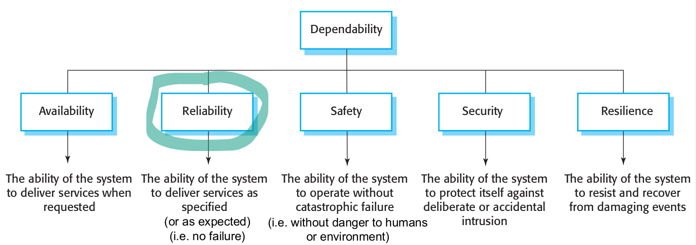
Software Reliability
Fault vs. Error vs. Failure
Fault
- defect in a system
- may or may not lead to a failure.
- For instance, although a system may contain a fault, its input and state conditions may never cause this fault to be executed, such that an error occurs; and thus that particular fault never leads to a failure.
- is usually referred to as a bug for historic reasons Error
- discrepancy between intended behaviour of system and actual behaviour inside system boundary
- occurs at runtime when some part of the system enters unexpected state due to activation of fault Failure
- instance in time when system shows behaviour contrary to its specification [or user expectations]
An error may not necessarily cause a failure, for instance, an exception may be thrown by a system, but this may be caught and handled using fault tolerance techniques, such that the overall operation of the system conforms to the specification.
Real-time Systems
Real-time system definition
- Mostly systems which monitor and control their environment
- usually embedded systems
- Inevitably associated with hardware devices
- sensors: collect data from the system environment
- actuators: change (in some way) the system's environment
- Time is critical!
- real-time systems MUST respond within specified times
- typically they must process data at least as quick as it arrives
- however, if data collection is faster than processing data must be buffered
- e.g. when collecting information about particle collisions at LHC@CERN
- circular or ring buffers are a mechanism for smoothing out small speed differences
- however, if data collection is faster than processing data must be buffered
- Mostly systems which monitor and control their environment
Soft real-time system and hard real-time system
- Soft real-time system is a system whose operation is degraded if results are not produced according to the specified timing constraints
- Hard real-time system is a system whose operation is incorrect if results are not produced according to the timing specification
Monitoring & Control Systems
- Monitoring systems act when exceptional sensor values are detected
- Control systems continuously control hardware actuators depending on value of associated sensor
Real-time design patterns
Channel pattern
- A channel can be thought of as a pipe* that sequentially transforms data from an input value to an output value.
- architectural pattern for RT systems
- internal elements work on data stream in a kind of factory automation process.
- each internal element performs relatively simple operations on data
- multiple elements of the data stream can be in different parts of the channel at the same time.
- A channel can be thought of as a pipe* that sequentially transforms data from an input value to an output value.
Advantages of multiple channels
- Multiple channels to improve quality
- Performance: throughput capacity can be increased by adding multiple homogeneous (identical) channels.
- Reliability: multiple channels can operate in various ways to achieve fault tolerance.
- Safety: multiple channels can improve safety by adding fault identification and safety measures.
- Multiple channels to improve quality
Safety & reliability patterns
Without Fail-Safe State
- Homogeneous Redundancy
- Triple Modular Redundancy
- Heterogeneous Redundancy
With Fail-Safe State
- Protected Single Channel Pattern
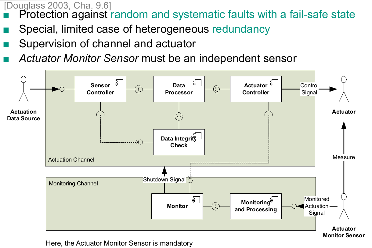
- Monitor-Actuator Pattern
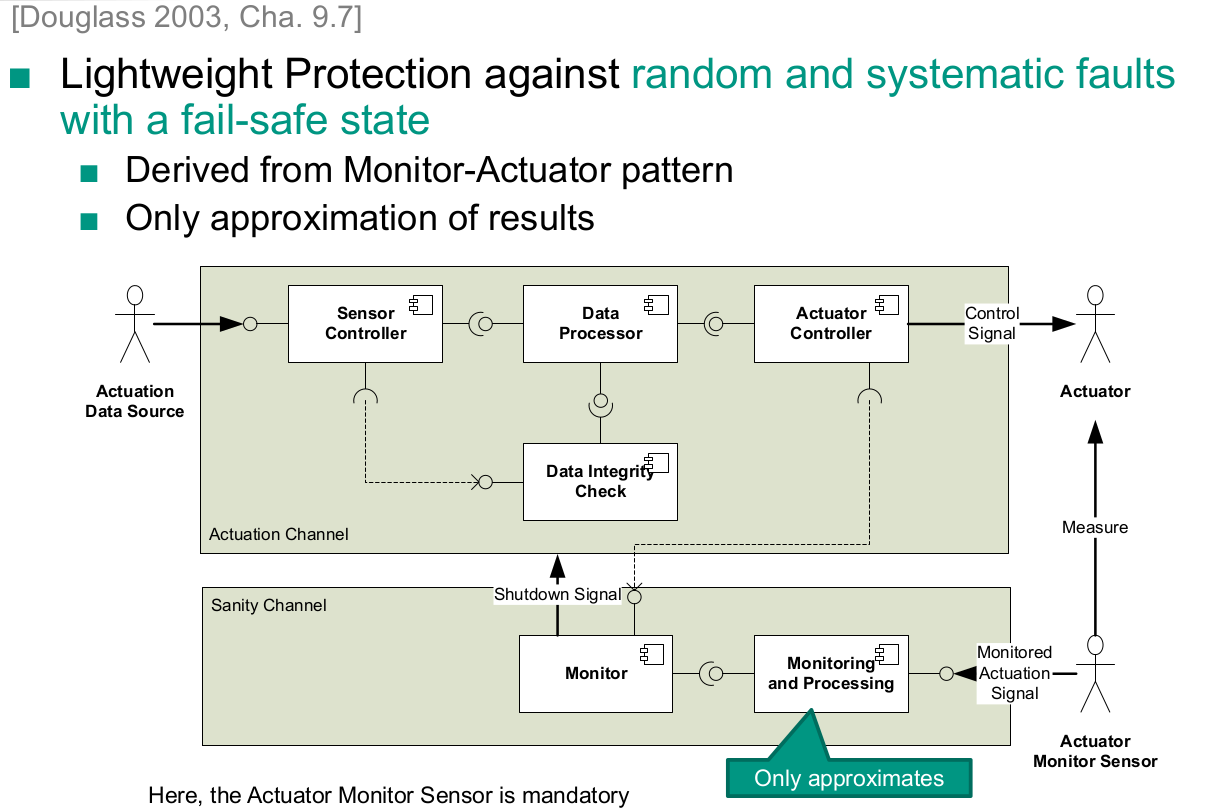
- Sanity Check Pattern
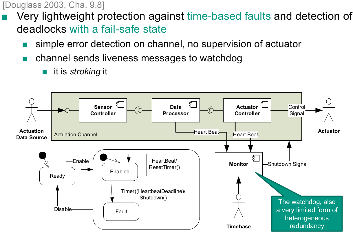
- Watchdog Pattern
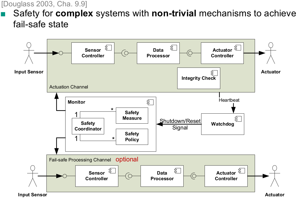
- Safety Executive Pattern
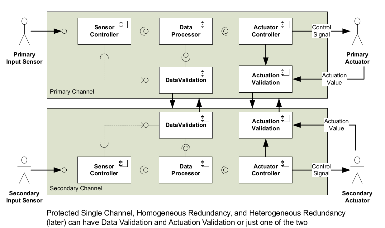
Homogeneous redundancy
Protection against random faults, not assuming a fail-safe state
Triple Modular Redundancy
- Protection against random faults without a failsafe state
- provides continuity of operation
- no validation needed
- Does this work to improve pure software solutions?
- Protection against random faults without a failsafe state
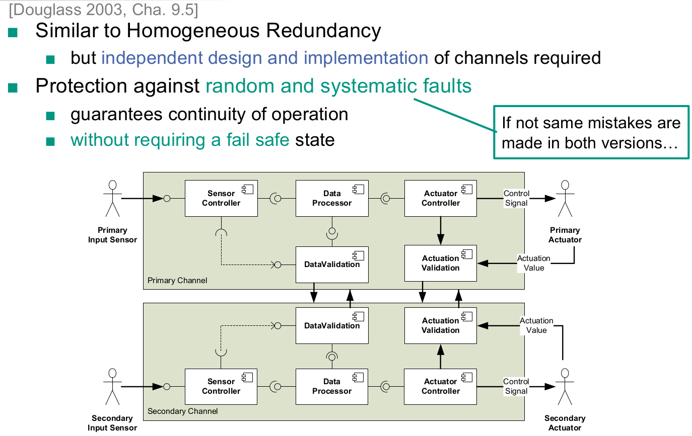
Heterogeneous Redundancy
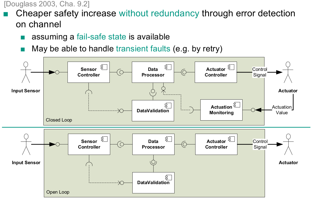
Protected Single Channel
Monitor-Actuator Pattern
Sanity Check Pattern
Watchdog Pattern
Safety Executive Pattern
Software Security
Principles for Building Secure Software
- Secure the weakest link
- Practice defence in depth
- Fail securely
- Secure by default
- Principle of the least privilege
- No security through obscurity (Kerkhoff’s principle)
- Minimize attack surface
- Privileged Core
- Input Validation and Output Encoding
- Don’t Mix Data and Code
Causes of insecure software
- Management constraints
- Bad design
- Faults in implementation
Security testing guidelines
- Most effective: Focus on identified risks
- Use a code coverage metric
- Perform code and system reviews
- Aim to evaluate security in each phase
- Use various sources for test cases
- Set up a standard security testing environment that checks „basics“
- Have security experts check your system as black box or white box
Learning Goals
Partials answers for the learning goal questions. I think it is valuable to review them, while learning for the exam. Some of these questions are just to broad to provide a short and comprehensive answer. Other questions are answered above in greater detail.
Clean Code
Reiterate coding best practices, including SOLID
Principles for good object-oriented design:
- SOLID
- Single responsibility principle
- Open-closed principle
- Liskov substitution principle
- Interface segregation
- Dependency inversion
- YAGNI
- Boy-Scout-Rule
- Information hiding principle
- Principle of least surprise
- Command-query separation
- Single Level of abstraction
- KISS
- DRY
- Coding conventions
- Naming
- No hints on context, type or metaclass
- Avoid unnecessary comments
- Formatting
- Rely on IDE
- Group related code blocks with blank lines
- Naming
- SOLID
- Identify violations of coding best practices
Refactor towards coding best practices
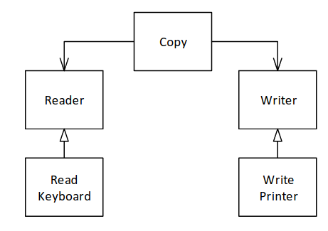
The only relevant and non-obvious refactoring here is dependency inversion in combination with the observer pattern
Apply template method and strategy pattern
Template method:

Strategy pattern:

Software Architecture
Reproduce and describe the definitions of software architecture
A software system’s architecture is the set of principal design decisions made about the system [Taylor et al., 2009, p.58]
The software architecture of a system is the set of structures needed to reason about the system, which comprise software elements, relations among them, and properties of both [Bass et al., 2013]
A software architecture
- is the result of a set of design decisions
- comprising the structure of the system
- with components and
- their relationships and
- their mapping to execution environments.
Explain Conway’s law
A system (usually) reflects the organizational structure of the organization that built it.
Explain the difference between software architecture and software architecture documentation
There is no difference. Software architecture is not the implicit documentation of the system, but always needs to be explicitly documented.
Describe the advantages of explicit architecture and the influences on architecture decisions
- Stakeholder communication
- System analysis
- Component reuse
Assign design decisions and elements to architectural layers
Explain the architectural style layered architecture
The system is divided into layers. Layers allow conceptual separation of software. Calls can only happen from high layers to lower layers. Allowing for independent replacement of a layer without changing other layers
- Apply model view controller and observer to examples
Clean architecture
Know underlying principles of clean architecture styles
- Depend in the direction of stability
- Taming cyclic dependencies
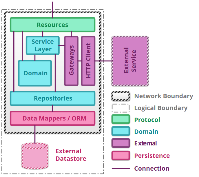
Know “circles” of the clean architecture style and how they are applied
- Core Enterprise Rules: Entities
- Business Rules: Use Cases
- Interface Adapters: Presenters, Controllers, Gateways
- Frameworks and Drivers: Database, UI, External Interfaces, Devices
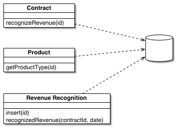
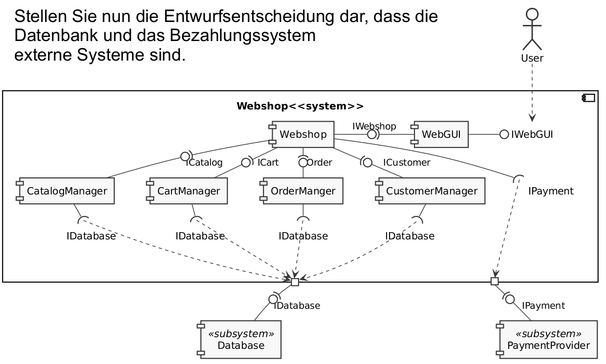
Apply dependency inversion to resolve violations to the clean architecture
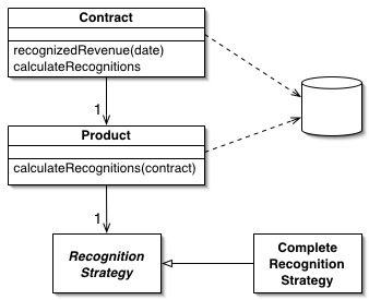
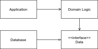
Enterprise architecture looks like this

However, having the dependency of domain logic to the database violates the rules of clean architecture
Enterprise Application Architecture
Characterize enterprise systems and decide which characteristics, a given application has
- concurrent data access
- multiple user interfaces
- external interfaces
- persistent data
- large amounts of data
- business rules not always coherent throughout the whole system
- conceptual dissonance
Describe patterns of structuring domain logic, data source architectural patterns, and object-relational structural patterns
Domain logic
Transaction script
Table module
Domain model
Data source architectural patterns
Record set
Active record
Row-data gateway
Table data gateway
Data mapper
Identity map
Object-relational structural patterns
Single table inheritance
Class table inheritance
Concrete table inheritance
- Apply a selected enterprise application pattern for a concrete design
Software Components
Understand and define component models
Component models define:
- What a component is
- How components can offer services
- How components can be discovered
- How components communicate
- How can components be composed
Read and write component diagrams
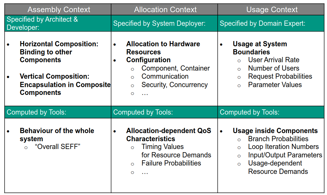
Describe the elements of the Palladio component model (PCM)
Palladio defines contexts and roles for these contexts
- Assembly context
- Software architect, component developer
- Allocation context
- System developer
- Usage context
- User, domain experts
- Assembly context
- Explain some of the design decisions made in the PCM
Know the influence factors for the performance of software components
Execution environment, usage profile, external system behaviour, component implementation
Domain driven design
Very brief here, but I wrote pretty detailed about DDD modelling already https://wachter-space.de/2020/08/30/ddd_rbm/
Know ideas and patterns underlying Domain-Driven Design
- Everything is organized into bounded contexts
- Core domain
- Supporting domain
- Shared kernel
- Generic subdomain
- Bounded context have a documented ubiquitous language that is consistently used, wherever applicable
- Bounded context interaction is made explicit in the context map
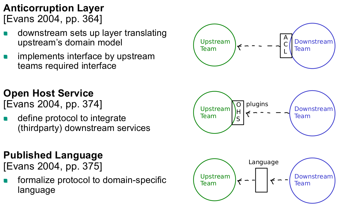
- Shared kernel
- Open host service
- Published language
- Conformist
- Supplier/consumer
- Anti-corruption layer
- In the tactical design, single bounded contexts are build using
- Value objects
- Entities
- Factories
- Aggregates
- Repositories
- Services
- Modules
- Everything is organized into bounded contexts
- distinguish and assign different building blocks to domain model
- specify additional support patterns to an existing domain model
- Distinguish different strategic designs
Microservices
Explain why Microservice is an architectural style
Architectural styles are solution principles, that are applied throughout the whole system. This is exactly what the microservices architectural principles do. In contrast, a microservice is not an architectural pattern, i.e., is used a limited number of times in some part of the system. That would be a service oriented architecture
Know the characteristics of Microservices
- Componentization via services
- Organized around business capabilities
- Products not projects
- Smart endpoints and dumb pipes
- Decentralized governance
- Decentralized data management
- Infrastructure automation
- Design for failure
- Evolutionary design
Explain the typical elements of a Microservice
Cloud Computing and Cloud Architecture
Know the differences between cloud computing and hosted resources regarding used technologies, software delivery model
Technology: Multi-tenancy via partitioning of resources implemented via virtualization (or paravirtualization or containerization) instead of partitioning via multiple hardware servers
Software delivery model: IaaS, PaaS, SaaS instead of license-based software delivery
Explain the economics of cloud computing
- Paid per usage (measured service)
- Good utilization of hardware, because the hardware is shared between customers (oversubscription)
- The customer saves operational costs and acquisition cost
Know and apply architectural principles of cloud software (8)
- Decentralization: Use fully decentralized techniques to remove scaling bottlenecks and single points of failure.
- Asynchrony: The system makes progress under all circumstances.
- Autonomy: The system is designed, such that individual components can make decisions based on local information.
- Local responsibility: Each individual component is responsible for achieving its consistency; this is never the burden of its peers.
- Controlled parallelism: Abstractions used in the system are of such granularity that parallelism can be used to improve performance and robustness of recovery or the introduction of new nodes.
- Decompose into small well-understood building blocks: Do not try to provide a single service that does everything for everyone, but instead build small components that can be used as building blocks for other services.
- Symmetry: Nodes in the system are identical in terms of functionality, and require no or minimal node-specific configuration to function.
- Simplicity: The system should be made as simple as possible (but no simpler).
Distinguish SaaS, PaaS, and IaaS and give examples for each
- Software as a service, e.g. Microsoft Office 365
- Platform as a service, e.g. AWS Lambda
- Infrastructure as a service, e.g. Netcup VServers
Software Container
Know the underlying kernel systems to develop and run containers
- Historically,
chrootwas used for file system isolation
- Docker is implemented using Linux namespaces, they isolate things like mounts, processes, network
- Name spaces are managed via
setns,clone,unshare
pivot_rootis used for file system isolation
- Historically,
Know the life-cycle of a container and functions of container runtimes
runc speccreates a base container configuration from content of current directory
runc create IDcreates the container ID given the configuration in the current directory
runc start IDstart the previously created container ID running its root process
runc pause / resume IDpause respectively resume a container’s operation
runc kill IDkills a container’s operation by sending the respective signal
runc listlists all containers managed as created, started, suspended, stopped
runc delete IDstop and remove the container from the host
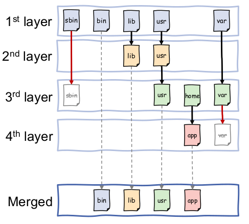
Know the concept of Layered File Systems
There is a base layer with a (small) set of files. Each layer on top makes changes to the underlying layers. This is useful for containers to share parts of the host file system such as libraries and for the container to make modifications that do not affect the host system. This is achieved by mounting N-1 layers into the container as read only and then have a copy on write mechanism to in the Nth layer
Know how to construct a container image with docker
Write a
Dockerfileand than usedocker bulid
Software Development Processes
Recognize and distinguish different types of process models
- Waterfall Model
- V-Model
- Spiral Model
- UP/RUP
Understand the evolutionary and incremental development
Incremental is growing the system in steps of multiple waterfalls
Evolutionary design is (trying) to build the whole system in one waterfall. Going through the waterfall again means a major overhaul of the system or building a new one
Describe the advantage of incremental over a sequential process
In practice requirements frequently change, iterative processes allow timely incorporation of the new requirements.
Describe the phases and disciplines of the Unified Process
Phases:
- Inception
- "Envision the project scope, vision, and business case" [Larman]
- Explore following kind of questions:
- "What is the vision and business case for this project?
- Feasible?
- Build and/or buy?
- Rough unreliable cost range: is it $10K – 100K or in the millions?
- Should we proceed or stop?" [Larman]
- Elaboration
- "is the initial series of iterations during which, on a normal project,
- the core, risky software architecture is programmed and tested
- the majority of requirements are discovered and stabilized
- the major risks are mitigated or retired" [Larman]
- "Build the core architecture, resolve the high risk elements, define most requirements, and estimate the overall schedule and resources" [Larman]
- "is the initial series of iterations during which, on a normal project,
- Construction
- "Iterative implementation of the remaining lower risk and easier elements, and preparation for deployment" [Larman]
- Transition
- "beta tests, deployment" [Larman]
Roles:
- Business Modeling
- Requirements
- Design
- Implementation
- Test
- Deployment
- Configuration & Change
- Management
- Project Management
- Environment
- Inception
Agile Development
Know agile development ideas and principles
- Customer collaboration over contract negotiation
- Individuals and interaction over processes and plans
- Working software over comprehensive documentation
- Responding to change over following a plan
Understand how to perform a project following an eXtreme Programming or Scrum process
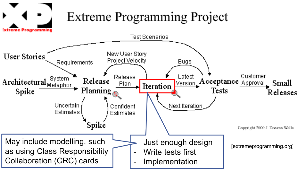
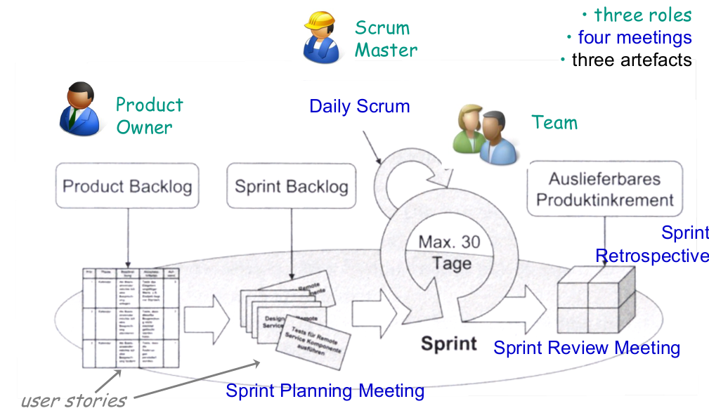
- Distinguish Unified Process, eXtreme Programming, and Scrum process
Discuss advantages and disadvantages of agile practices
- Good:
- Agile projects do not assume a stable world.
- Fast feedback on customer satisfaction and product quality essential
- Disciplined Process (certainly not ad hoc!)
- Shifts responsibility to each team member.
- Problematic:
- Unclear how to include architectural design in agile projects.
- Unclear how to scale to larger projects, unclear how to do planned reuse.
- “Keep the architecture flexible” is not the complete answer, as some design decisions are by nature hard to revert.
- Shifts responsibility to each team member (not everyone wants to live with this pressure)
- Some dogmatism: relevance of scientific empirical evidence sometimes neglected: e.g., pair programming helps to improve quality early. However, they are less cost-effective than reviews (which help likewise in quality).
- Agile methods are a good manufacturing approach. But can we become an engineering discipline?
- Good:
Requirements Engineering
- Describe the terms and activities of Requirements Engineering
classify and assess requirements according to the facets kind and representation
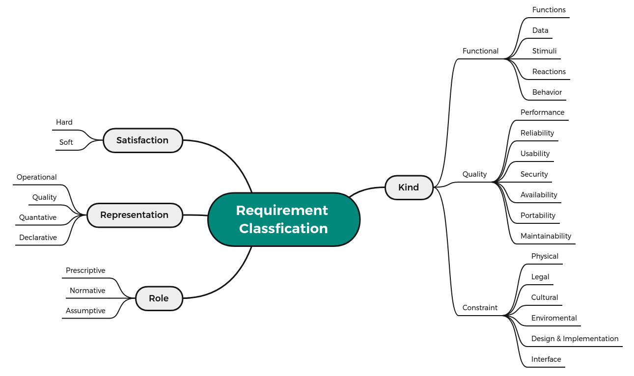
Apply fundamental guidelines on specifying natural language requirements
- Short sentences, one clear requirement per sentence
- Use active language that makes clear who is responsible for what
- Avoid “weak” words, such as effective, consequently, user-friendly, easy, quickly, timely, reliable, appropriate
- Maintain a glossary of terms
Use Cases
- Describe the purpose and the elements of use case diagrams
Classify use cases according to their level and goal
- User-Goal
- Sub-Goal
- Operation
- create use case diagrams and “fully-dressed” use cases
- describe their role in the software development process
Software Quality – Reliability
Know and distinguish different kinds of software qualities
- Usability
- Reliability
- Functionality
- Maintainability
- Portability
- Efficiency
Explain the concept of a real-time system
A real time system not only needs to execute required functionality correctly, but also needs to do so within a specified (short) timeframe.
Distinguish between different types of real-time systems
- Hard vs soft real-time systems
- soft: operation is only degraded
- hard: operation is incorrect
- Monitor vs control systems
- Control: Continuously control an actor
- Monitor: Only use an actor, if a threshold has been measured
- Hard vs soft real-time systems
Select a suitable safety and reliability pattern for a given system
Without Fail-Safe State
- Homogeneous Redundancy
- Triple Modular Redundancy
- Heterogeneous Redundancy With Fail-Safe State
- Protected Single Channel Pattern
- Monitor-Actuator Pattern
- Sanity Check Pattern
- Watchdog Pattern
- Safety Executive Pattern
Software Quality – Security
- Know fundamental ideas and challenges of software security
- Recognize common security problems and know means to avoid them